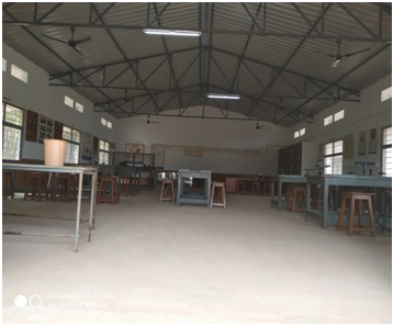
ENGINEERING WORKSHOP
Workshops were the only places of production until the advent of industrialisation and the development of larger factories. Engineering workshop is the laboratory which provides both the area and tools (or machinery) that may be required for the manufacture or repair of manufactured goods. Here the students will learn the basics about Carpentry, Fitting, Tin Smithy, Black Smithy and House Wiring.
Lab In charge:Mr. B. HARI KRISHNA
Name Of The Technical Staff: Mr. P BHASAKARA RAO
- COURSE CONTENT
1. Demonstration: Safety practices and precautions to be observed in workshop.
2. Wood Working: Familiarity with different types of woods and tools used in wood working and make following joints.
a) Half – Lap joint b) Mortise and Tenon joint c) Corner Dovetail joint or Bridle joint
3. Sheet Metal Working: Familiarity with different types of tools used in sheet metal working,
Developments of following sheet metal job from GI sheets.
a) Tapered tray b) conical funnel c) Elbow pipe d) Brazing
4. Fitting: Familiarity with different types of tools used in fitting and do the following fitting
Exercises.
a) V-fit b) Dovetail fit c) Semi-circular fit d) Bicycle tire puncture and change of two-wheeler tire
5. Electrical Wiring: Familiarity with different types of basic electrical circuits and make the
Following connections.
a) Parallel and series b) Two-way switch c) Godown lighting d) Tube light e) Three phase motor f)
Soldering of wires
6. Foundry Trade: Demonstration and practice on Moulding tools and processes, Preparation of
Green Sand Moulds for given Patterns.
7. Welding Shop: Demonstration and practice on Arc Welding and Gas welding. Preparation of Lap joint and Butt joint.
8. Plumbing: Demonstration and practice of Plumbing tools, Preparation of Pipe joints with
Coupling for same diameter and with reducer for different diameters.
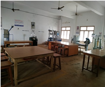
MECHANICS OF SOLIDS LAB
Mechanics of solids is the branch of continuum mechanics that studies the behaviour of solid materials, especially their motion and deformation under the action of forces,temperature changes, phase changes, and other external or internal agents. The Mechanics of Solids Laboratory is a facility dedicated to the structural testing and design of components and materials.
Lab In charge: Dr. G. SATISH
Name Of The Technical Staff: Mr. V MURALI KRISHNA
LIST OF EXPERIMENTS:
Estimate young‟s modulus of wood/steel materials Direct Tension test on Universal Testing Machine (UTM)
Bending test on simply supported beam steel.
Bending test on simply supported beam Wood.
Bending test on cantilever beam Steel
Torsion test
Brinell‟s hardness test
Rockwell hardness test
Test on Tension springs.
Test on Compression springs
Compression Test on wood.
Charpy Impact test.
Izod Impact test.
METALLURGY LAB
The main objective of this laboratory is to learn about the properties of various materials like metals, ceramics, glasses, organic plastics, polymers etc. Metallurgy deals with the science technology of heat treatment of metals and alloys. Instrumentation deals with the basic knowledge on mechanism of an instrument.
Lab In charge: Mr. V.V.N.SARATH
Name Of The Technical Staff: Mr. A S N MURTHI
LIST OF EXPERIMENTS:
Preparation and study of the Microstructure of Al
Preparation and study of the Microstructure of Cu
Preparation and Study of the Microstructure of Gray Cast-iron.
Preparation and Study of the Microstructure of Stainless steel
Preparation and Study of the Microstructure of Brasst
Preparation and Study of the Microstructure Malleable Cast Iron
FLUID MECHANICS & HYDRAULIC MACHINES LAB
The purpose of this laboratory is to reinforce and enhance our understanding of the fundamentals of Fluid mechanics and Hydraulic machines. The experiments here are designed to demonstrate the applications of the basic fluid mechanics principles and to provide a more intuitive and physical understanding of the theory. The main objective is to introduce a variety of classical experimental and diagnostic techniques, and the principles behind these techniques.
Lab In charge: Mr. A. PHANI BHASKAR
Name Of The Technical Staff: Mr. P BHASAKARA RAO
LIST OF EXPERIMENTS:
Impact of jet on vanes
Performance test on Pelton wheel-constant head
Performance test on Pelton wheel-constant speed
Performance test on Francis turbine-constant head
Performance test on Francis turbine-constant speed
Performance test on single stage centrifugal pump
Performance test on multi stage centrifugal pump
Performance test on Reciprocating pump
Calibration of Venturimeter.
Calibration of Orificemeter
Determination of Friction factor for a given pipe line
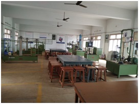
PRODUCTION TECHNOLOGY LAB
Production Technology is subject which provide a position to set up and operate production dealing with Welding, Casting, rolling, plastic moulding etc. The main objective of the laboratory is to understand different manufacturing techniques by studying different processes in Production Technology.
Lab In charge: Mr. P. RAM PRASAD
Name Of The Technical Staff: Mr. G SOMARAJU
LIST OF EXPERIMENTS:
I.METAL CASTING:
1.Pattern Design and making – for one casting drawing.
2.Sand properties testing – for strength and permeability
3.Mould preparation, Melting and Casting
II.WELDING:
1.Manual metal arc welding – Lap & Butt Joints
2.Resistance Spot Welding
3.Brazing and soldering
4.Gas cutting.
5. TIG/MIG Welding
6.Gas welding
III.METAL FORMING AND POWDER METALLURGY:
1.Blanking & Piercing operations and study of simple, compound and progressive dies.
2.Deep drawing and extrusion operations.
3.Bending and other operations
4.Basic powder compaction and sintering
IV.PROCESSING OF PLASTICS:
1.Injection Moulding
2.Blow Moulding

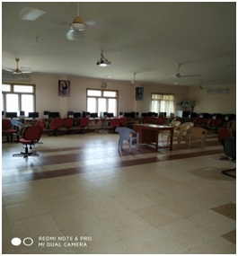
CAD LAB
Nowadays as the technology improving more and more we no longer require the use of protractors and compasses to create drawings, instead there are several classes that focus on the use of various software.This laboratory mainly deals with the detailed engineering of 3D models and/or 2D drawings of physical components using CAD software, but it is also used throughout the engineering process from conceptual design and layout of products, through strength and dynamic analysis of assemblies to definition of manufacturing methods of components. It can also be used to design objects.
Lab In charge: Mr. G.V.N.SANTHOSH
Name Of The Technical Staff: Mr. Ch. SYAM PRADEEP KUMAR
LIST OF EXPERIMENTS:
DRAFTING: Development of part drawings for various components in the form of orthographic and isometric representation of dimensioning and tolerances scanning and plotting. Study of script, DXE and IGES files.
PART MODELING: Generation of various 3D models through protrusion, revolve, shell sweep. Creation of various features. Study of parent child relation. Feature based and Boolean based modeling surface and assembly modeling. Study of various standard translators. Design simple components. Generative drafting exercises.
Import CAD model into analysis software and carry out the following
a) Determination of deflection and stresses in 2D and 3D trusses and beams.
b) Determination of deflections component and principal and Von-mises stresses in plane stress, plane strain and Axisymmetric components.
c) Determination of stresses in 3D and shell structures (at least one example in each case).
d) Estimation of natural frequencies and mode shapes, Harmonic response of 2D beam.
e) Steady state heat transfer Analysis of plane and Axisymmetric components
Packages to be provided to cater to drafting, modeling & analysis from the following:Micro Station, CATIA, Pro-E, I-DEAS, ANSYS, NISA,CAEFEM, ABACUS etc.
THEORY OF MACHINES LAB
Theory of Machine Lab may be defined as that branch of Engineering-science, which deals with the study of relative motion between the various parts of a machine, and forces which act on them. The main objective of Theory of Machines lab is to impart practical knowledge on design and analysis of mechanisms for the specified type of motion in a machine. Demonstration exercises are provided with wide varieties of transmission element models to understand machine kinematics. Various experiments with governors, gyroscopes, balancing machines and universal vibration facilities are available to understand machine dynamics.
Lab In charge: Mrs. K.ARAVINDA
Name Of The Technical Staff: Mr. P BHASAKARA RAO
LIST OF EXPERIMENTS:
To determine whirling speed of shaft theoretically and experimentally.
To determine the position of sleeve against controlling force and speed of a Hartnell governor and to plot the characteristic curve of radius of rotation.
To analyze the motion of a motorized gyroscope when the couple is applied along its spin axis.
To determine the frequency of undamped free vibration of an equivalent spring mass system.
To determine the frequency of damped force vibration of a spring mass system.
To study the static and dynamic balancing using rigid blocks.
To find the moment of inertia of a flywheel.
To plot follower displacement Vs cam rotation for various Cam Follower systems.
To plot slider displacement, velocity and acceleration against crank rotation for single slider crank mechanism/Four bar mechanism.
To find coefficient of friction between belt and pulley.
To study simple and compound screw jack and determine the mechanical advantage, velocity ratio and efficiency.
To study various types of gears- Spur, Helical, Worm and Bevel Gears.

THERMAL ENGINEERING LAB
The objective of this laboratory is to introduce the student to the fundamental and industrial theories of working of IC engines, modes of Heat transfer, principles of refrigeration and air conditioning etc. The Thermal Engineering Laboratory is equipped with several test facilities for doing research within thermal processes for energy conversion.
Lab In charge: Mr. N. RAGHUVEER
Name Of The Technical Staff: Mr. V MURALI KRISHNA
LIST OF EXPERIMENTS:
I.C. Engines valve / port timing diagrams
I.C. Engines performance test (4 -stroke diesel engines)
I.C. Engines performance test on 2-stroke petrol.
Evaluation of friction power by conducting morse test on 4-stroke multi Cylinder petrol engine.
Determination of friction power by retardation and motoring test on IC engine.
I.C. Engines heat balance.
Economical speed test of an IC engine.
Performance test on variable compression ratio engines.
Performance test on reciprocating air compressor unit.
Study of boilers
Dis-assembly / assembly of Engines.
Load test on 4 – stroke single cylinder variable compression ratio petrol engine.
Performance test on Refrigeration test rig.
MACHINE TOOLS LAB
The main objective of this laboratory is to provide basic concepts of measurements by using different techniques and knowledge on different machines like lathe, shaper, planner etc. The student will be in a position to take up assignments in inspection of mechanical components in a medium to large manufacturing unit.
Lab In charge: Mrs. P. GAYATHRI
Name Of The Technical Staff: Mr. G SOMARAJU
LIST OF EXPERIMENTS:
1.Introduction of general purpose machines
Lathe
Slotting Machine
Drilling Machine
Tool and Cutter Grinder
Milling Machine
Tool and Cutter Grinder.
Shaper.
Cylindrical grinder.
Planing Machine.
Surface Grinder.
2.Plain turning and facing operations on lathe. (To be discussed)
3.Step turning and taper turning operation on lathe.
4.Thread cutting and knurling operation on lathe.
5.Drilling operation on lathe
Fundamental operations on
6.Drilling and tapping.
7.Shaping and planning.
8.Slotting.
9.Milling.
10.Cylindrical surface grinding.
11.Grinding of tool angles.
12.Introduction of CNC machine tools

HEAT TRANSFER LAB
Heat Transfer laboratory provides knowledge about modes of heat transfer and also provide different applications on parallel and counter flow heat exchanger and heat pipes. The student gains knowledge about the modes of heat transfer like conduction, convection and radiation.
Lab In charge: Mr.A.YESWANTH
Name Of The Technical Staff: Mr. G SOMARAJU
LIST OF EXPERIMENTS:
Determination of Overall heat transfer co-efficient Composite Slab Apparatus
Determination of Heat transfer through a lagged pipe.
Determination of Heat Transfer through a Concentric Sphere
Determination of Thermal Conductivity of given metal rod.
Determination of Heat transfer in pin-fin
Determination of Heat transfer in forced & natural convection apparatus.
Determination of Parallel and counter flow heat exchanger.
Determination of Emissivity of a given surface .
Determination of Stefan Boltzmann constant.
Determination of Heat transfer in drop and film wise condensation.
Determination of Critical Heat flux.
Study of heat pipe and its demonstration.
COP of VCR System with Capillary and thermal expansion valve.
Determination of thermal conductivity of liquids and gases.

METROLOGY & INSTRUMENTATION LAB
The Metrology and instrumentation Laboratory course is designed for measuring and gauging instruments for inspection of precision linear, geometric forms, angular and surface finish measurements. The student can learn the measurements with and calibration of instruments. They also understand the machine tool alignment test. Instrumentation lab introduces the students with the theory and methods for conducting experimental work in the laboratory and calibration of various instruments for measuring pressure, temperature, displacement, speed, vibration etc.
Lab In charge: Ms. K. TULASI
Name Of The Technical Staff: Mr. Ch. SYAM PRADEEP KUMAR
LIST OF EXPERIMENTS:
Measurement of lengths, heights, diameters by vernier calipers, micrometers, slip gauges etc.
Measurement of bores by internal micrometers and dial bore indicators.
Use of gear tooth vernier caliper for tooth thickness inspection and flange micro meter for checking the chordal thickness of spur gear.
Machine tool alignment test on the lathe.
Machine tool alignment test on drilling machine.
Machine tool alignment test on milling machine.
Angle and taper measurements with bevel protractor, Sine bars, rollers and balls.
Use of spirit level in finding the straightness of a bed and flatness of a surface.
Thread inspection with two wire/ three wire method & tool makers microscope.
Surface roughness measurement with roughness measuring instrument.
SIMULATION LAB
Computational fluid dynamics (CFD) is a branch of fluid mechanics that uses numerical analysis and data structures to analyze and solve problems that involve fluid flows. Computers are used to perform the calculations required to simulate the free-stream flow of the fluid, and the interaction of the fluid (liquids and gases) with surfaces defined by boundary conditions. With high-speed supercomputers, better solutions can be achieved, and are often required to solve the largest and most complex problems.
Lab In charge: Mr. Godasu V N Santhosh, Associate Professor
Name Of The Technical Staff: Mr. M. Venkata Krishna
LIST OF EXPERIMENTS:
Writing Programs in C and MATLAB for the following:
Solution of Transcendental equations
Solution of Simultaneous algebraic equations
Numerical differentiation and Integration
Solution of Ordinary Differential Equation
Solution of a Tri-diagonal matrix using Thomas Algorithm
Solution of Partial differential equations related to
i.Elliptical Partial differential equations
ii.Parabolic Partial differential equations
iii.Hyperbolic Partial differential equations
7.Solution of 1-D and 2-D heat conduction with (Finite Difference method)
i.Constant temperature boundary conditions
ii. Constant heat flux boundary conditions
iii. Convective boundary conditions
8.Solution of Incompressible Navier-Stokes equations (Finite difference and Finite Volume methods)
9.Solution of Inviscid incompressible fluid flows.(Finite difference and Finite Volume methods)
Using ANSYS-FLUENT solve the following problems of heat transfer analysis:
Steady state conduction
- Lumped heat transfer
Convective heat transfer – Internal flow (study both velocity and thermal boundary layers)
Convective heat transfer – External flow (study both velocity and thermal boundary layers)
Radiation heat transfer– Emissivity

CAM LAB
Computer-aided manufacturing (CAM) uses geometrical design data to control automated machinery. CAM systems are associated with computer numerical control (CNC) or direct numerical control (DNC) systems. These systems differ from older forms of numerical control (NC) in that geometrical data are encoded mechanically. Since both CAD and CAM use computer-based methods for encoding geometrical data, it is possible for the processes of design and manufacture to be highly integrated. Computer-aided design and manufacturing systems are commonly referred to as CAD/CAM.
Lab In charge: Mr. M.SUNIL RAJ
Name Of The Technical Staff: Mr. Ch. SYAM PRADEEP KUMAR
LIST OF EXPERIMENTS:
- Study of various post processors used in NC
- Machining of simple components on NC lathe and Mill by transferring NC Code / from a CAM package.
- CNC part programming Entry and
- Practices on CNC Turning
- Programming for facing
- Programming for Turning
- Programming for Linear and Circular
- Programming for Facing
- Programming for Multiple Facing
- Programming for Grooving
- Practice on CNC Milling
- Programming using linear and circular
- Programming using Sub-Program.
- Programming for Mirroring
- Programming for Circular Pocket Milling
- Programming for Rectangular Pocket milling
- Programming for Drilling
Automated CNC Tool path & G-Code generation using Pro/E/Master CAM
MECHATRONICS LAB
Mechatronics is the synergistic integration of mechanical engineering, electrical engineering, electronics, computer science, and control theory for the design of intelligent systems. Mechatronic systems are used in automotive systems, aerospace systems, consumer electronics, and robotics.
Lab In charge: Mr. D. J JOHNSON
Name Of The Technical Staff: Mr. A S N MURTHI
LIST OF EXPERIMENTS:
PLC PROGRAMMING
a. Ladder programming on Logic gates ,Timers & counters
b. Ladder Programming for digital & Analogy sensors
c. Ladder programming for Traffic Light control, Water level control and Lift control Modules
AUTOMATION STUDIO software
a.Introduction to Automation studio & its control.
b.Draw & Simulate the Hydraulic circuit for series & parallel cylinders connection
c.Draw & Simulate Meter-in, Meter-out and hydraulic press and clamping.
MATLAB Programming
a. Sample programmes on Matlab/SIMULINK
b.Simulation and analysis of PID controller using SIMULINK

APPLIED ROBOT CONTROL LAB
ARC in collaboration with German University and APSSDC is the best tool to learn Industrial robotics through Project Based Learning (PBL). Through ARC student will get Real-time German technology training in the campus itself with skill on advanced technologies in Mechatronics & Industrial Robotics.
OBJECTIVES:
- Bringing latest technologies in automation and manufacturing sectors to the labs of colleges. Firsthand experience on industrial robots for the students to learn with industry-driven production requirements.
- Real-time training to supplement students with skill on advanced technologies to make them standout in global arena for immediate absorption into research and Industry.
- To train students and faculty members in the fields of Mechatronics & Industrial Robotics by German experts, extending hand holding support in upgrading skill sets of the students to global standards.
OUTCOME: The student will be able to
- Understand the importance of robot dynamics.
- Plan robot motions and paths.
- Familiarize with the most common robot sensors and understand fundamental sensor processing. Perform kinematics analysis of robot systems.
- Create, modify and execute different robot programs.
Lab In charge: Mr. G.V.N.SANTHOSH
Name Of The Technical Staff: Mr. A S N MURTHI